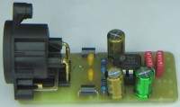
Balanced Audio Line Driver

This project is an application of the THAT1646
This project is complementary to one I posted on Elektor Labs:
https://www.elektormagazine.fr/labs/line-receive-with-rfi-and-dc-protect,
Here, it is an asymmetrical / symmetrical converter allowing to attack audio transmission lines.
The heart of the system is based on the THAT1646 which, with few external components, performs the function of a differential amplifier. The SSM2142 & DRV134 are fully compatible with this DIP8.
So let's come to the very ergonomic diagram.
C1, C4 & C5 are link capacitors to block all input and output DC components. R1, R4, R5 are pull down resistors. L1 C6 and L2 C7 constitute the RFI filtering.
L1 & L2 of 10 µH can be replaced by Ferrite Beads.
The Neutrik NC3MAH A-series connector is placed on the PCB. Components do not extend beyond the width of the connector, allowing for clamping when casing.
As usual, I always leave the possibility of disengaging pin 1 by a jumper during Earth, Ground, Chassis conflicts. You can also place a Lift Ground switch here.
C2 & C3 are decoupling capacitors. 22 ohm R2 & R3 plug into the ±15V power bus.
Personally, I use the That1646 with its That1240 complementary circuit in a signal distributor application. I am not confronted with the 48V of the phantom power supplies of microphone preamps. In its datasheet, the manufacturer, despite certain internal protections, recommends the use of 4 diodes which bring overvoltages to the V+ & V- rails.
Keep in mind that some commercial mixers send 48V globally to all the microphone inputs. I much prefer an individual key and not send 48V if it is not necessary.


Updates des Autors