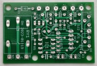
Board for simple microcontroller projects

One small board which can be used for more than one microcontroller project
During the last 5 years I have posted a couple of projects on Elektor Labs, which have 2 things in common:
- They use a member of the PIC12F microcontroller family
- There is no PCB, because a left over PCB from some other project is used with a lot of patches
Time for a change!
Therefore I created a small (37x55 mm) PCB, which can be used for a number of my projects by mounting the required components and eventually connecting some jumpers. Common components for (allmost) all projects are:
- a relay with driver transistor
- a LED to signalize an activated relay
- an 8 pin socket for a PIC12Fxxx microcontroller
- a basic power supply with a 78L05 (optional)
- 2 jumpers, for instance for reset and setup
- a 5 pin connector to program the PIC or to connect peripheral devices
The schematic contains all components possible, which will (an can) never be placed on the PCB at the same time.
At this moment I am working on the hardware and software to test the projects involved. Software has to be changed (a little bit) because of swapped microcontroller pins.
As soon as a project is ready I will add the result to the project page concerned. For any project also the partslist for the board will be included.
Simple test program
To check some of the functions of the board I made a simple test program. It runs on one of the simplest microcontrollers of the PIC12 family, the PIC12F509. Even such a small chip can be programmed in the C-language. The program has 2 functions: If jumper JP1 is open the relay is activated by connecting X3-X4 and it is de-activated by connecting X1-X2. If JP1 is connected only X1-X2 is used to activate and de-activate the relay
Projects ready
1 - burglar alarm
2 - electronic lock
3 - digital timer
4 - morse code generator
5 - exposure timer
6 - game assistant
7 - bathroom ventilation timer
8 - universal IR remote switch
9 - dmx512-with-pic-microcontrollers
10 - toothbrush timer


Updates des Autors