19 in a box

Update ! PCB is finish for test !Software: Neopixel control was implemented ! (up to 8-RGB-LED's)
Update ! PCB is finish for test !
Software: Neopixel control was implemented ! (up to 8-RGB-LED's)
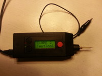
ELWMS 2.0, the multitool with new hardware and additional functions: - Buzzer was added for sound indication (High, low) - Higher output frequency up to 4 Mhz - USB-Uart (transmission of measurement data, firmware upload) - 3 push-buttons - Voltage measurement up to 15 VDC - Servo-Out (1-2ms signal to control servos, controlled by push-buttons) - Toggle-Out (High/Low controlled by push-buttons) - DCF 77 decoding - NMEA decoding And more could follow... -difference voltage measurement/hold function -neopixel controling -DS1820 temperature decoding if detected in 1-wire mode
Diskussion (4 Kommentare)
tdsnet vor 9 Jahren
Hi, the schematic link is dead.
It's possible to reactivate?
Thanks a lot
tuecok vor 9 Jahren
tdsnet vor 9 Jahren
Hi, the schematic link is dead.
It's possible to reactivate?
Thanks a lot
JohnHind vor 9 Jahren
As I commented on the earlier version, I'm still not getting the need for the analog switch between the probe and the MPU. I would simply connect the probe direct to all the MPU IO pins and make sure in firmware that a maximum of one of these pins was driving as an output at any time. The other pins should not be harmed (by any voltage between 0 and VCC) as long as they are configured as high impedence inputs.
Also the I do not quite get the circuitry around IC3 and IC4. Is this all about measuring up to 15v? Would it not be simpler to use a resistive divider to divide the input by 3 to keep the range within 0-5v?
JohnHind vor 9 Jahren
tuecok vor 9 Jahren
Frank Sauer vor 9 Jahren