
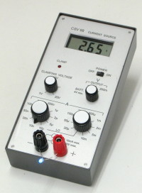
Adjustable DC current source with integrated hi-z DVM [130287-I]
With this portable instrument, you can safely test and measure very quickly all diodes, zeners, LEDs, etc... in their actual conditions of use, that is with a known and adjustable current, and up to a significant voltage (opposite to classic DVMs : unknown current, output limited to 3V or less).
With this portable instrument, you can safely test and measure very quickly all diodes, zeners, LEDs, etc... in their actual conditions of use, that is with a known and adjustable current, and up to a significant voltage (opposite to classic DVMs : unknown current, output limited to 3V or less). You can see the light efficiency from a LED, connect LEDs in series to make a visual selection, characterize a zener knee, estimate the leakage current of a diode with temperature, measure the avalanche voltage of a junction, measure very high resistances up to 2 gigaohms, and even capacitors with help of ... a stopwatch !
You can also disconnect the current source and use the instrument as a simple DVM with the particularity of a very high input impedance.
Main characteristics :
20 output current values from 10nA up to 20mA in 1-2-5 steps.
1.4% + 100pA output current precision
20V maximum output voltage.
Adjustable output clamping voltage from 1V up to 20V with LED indicator.
Integrated 3.5 digits two-range high impedance voltmeter.
0.2% voltmeter precision
4 x AA cells power supply.
110 hours battery life @ 1mA output
Diskussion (6 Kommentare)