
Audio switching with DG403 control extension
Erryson has published an audio switch based on a DG403 (https://www.elektormagazine.com/labs/audio-switching-with-dg-403). Previously, he asked me to create a small circuit to control it by a push button offering 2 possibilities: * Switching is only done when the push button is pressed continuously, * Switching is maintained or not at each short press on the push button; This is a "software switch" function. Since a push button does not naturally allow these 2 functions, it was associated with a PIC 12f629
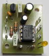
As we do not need many outputs, a PIC 12F629 was chosen because this reference is still well distributed among the general public. The diagram is quite simple in itself. 2 pins are used as inputs. One (2) is used to select the mode by a switch and can be replaced by a jumper if the desired function must not be modified during use. The second (3) is used for our push button. An anti-bounce is provided by C1 but also managed by the firmware 3 pins of the PIC are used as outputs. One (5) is used to signal the selected mode of use (Latch or Pulse). Output 7 (Q) is the normal output corresponding to the selected mode. Output 6 is the inverse output of 7. That is to say that if 7 is at 1, 6 will be at 0 and vice versa. An example of PCB is provided in the appendix. The firmware was written with MikroE compilers (https://www.mikroe.com/). Also in the appendix, you will find the source for these 3 languages Pascal, Basic and C. These compilers in demo mode allow you to compile up to 2K of firmware. This makes you autonomous to modify the source according to another PCB routing (Modification of the allocation of inputs and outputs to the PIC). One last note, do not look for quartz for this type of pic. The oscillator is internal to the pic which makes them pleasant to use in case of lack of space.
Club AC-News
Updates des Autors