
Model Car controled by Phone
WiFi + ESP32 + Smartphone = Remote Control Is it possible to control a car using a smartphone? That question intrigued me. Since most people carry a smartphone everywhere, it would be convenient to use one as a remote control. As a proof of concept, I added an ESP32 to a model car, wired the components, wrote the software, and conducted some tests. Here’s what I discovered…
By Huub Zegveld (The Netherlands)
As mentioned, I chose an ESP32 BoB (Board of Breakout) for its built-in microcontroller and Wi-Fi capabilities. Connecting the ESP32 to a local Wi-Fi network is straightforward. Setting up a simple server to accept commands via a web interface is also relatively easy. If you plan to use the PCB I designed in KiCad v6 (see Figure 1), make sure to choose the correct ESP32 module, as there are many variants available. Mine features a USB-C connector, printed Wi-Fi antenna, and most importantly, 2×15-pin headers (see Figure 2).
I designed not only the electronics and software but also the mechanical frame of the car myself. I used FreeCAD 0.21(note: version 1.0 is now available) and printed the chassis using UltiMaker Cura. Figure 3 shows the CAD model of the frame.
During testing, I found it inconvenient to check my router’s settings or connect the ESP32 to a PC via USB just to discover its IP address. A more elegant solution was to add a small OLED display to the car to show the assigned IP. I also wanted features like collision avoidance and lighting, so I included an ultrasonic sensor and LEDs.
Software
I used Arduino IDE 2.3.6 [1] as the primary development environment. My initial attempts were with a 433 MHz RF module, and I was able to reuse code, such as dc-motor.h. I did face some issues with ESP32 PWM functions, but after online research, I could resolve them.
The code for dc-motor.h and dc-motor.cpp was originally written in CodeBlocks IDE [2]. I employed several key libraries:
- WiFi.h – for Wi-Fi connection and server setup
- dc-motor.h – for PWM setup and motor control
- Adafruit_SSD1306.h, Wire.h, Adafruit_GFX.h – for OLED integration
Principle of operation
No additional software is required on the smartphone—just a browser connected to the same Wi-Fi network as the carrespectively the ESP32. The ESP32 obtains an IP address from your router’s DHCP server (e.g., 192.168.178.213), which is shown on the OLED display (see Figure 4).
Entering this IP in the browser of the smartphone sends an HTTP request to the ESP32’s webserver, which responds with a basic HTML control page (see Figure 5). Tapping a command like “stop” triggers another request, e.g., http://192.168.178.213/start=stop, which the ESP32 interprets to stop the car. That’s all.
The HC-SR04 ultrasonic sensor uses pulses that are inaudible to humans. The trigger pin (GPIO14, Pin 11 on ESP32) initiates a pulse, while the echo pin (GPIO12, Pin 12) signals receiving the reflected echo. The time delay is measured using the function pulseIn(Echo,HIGH), and the distance is calculated via the formula:
distanceCm = duration * SOUND_SPEED / 2.
If an object is detected within 20 cm, the car stops and reverses. For further details and example code, refer to the Handson Technology guide [6].
Hardware
For this project a usual BOM like the Componen List may not be fully sufficient, so here are some key details:Besides the ESP32 module with 30 pins, a motor driver is required. For this, I chose the integrated L293D solution. Next is the OLED display: a low-cost module connected via I2C is enough. I opted for one with a standard 0.96’’ diagonal and a resolution of 128×64 pixels (type SSD1306 or similar). Larger sizes are available – such as 1.3’’ (SSH1106) or 2.42’’ (SSD1309) – in various colors (white, blue, green, and yellow) that might work without modification, although I have not tested them. For collision detection, I included the HC-SR04 ultrasonic module, which is widely available at low cost. Since the car is powered by a 12 V source, a 7805 voltage regulator is needed to supply 5 V to the ESP32.
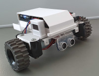
In addition to the electronic components, some mechanical parts are naturally required. As mentioned, the chassis is 3D-printed. For the wheels and motors, I repurposed parts from an old robot vacuum cleaner. The motors were of 12 V type, making the power supply straightforward. Naturally, bolts and nuts were also used. The completed model car is shown in Figure 6.
Circuit
The circuit diagram in Figure 7 shows the interconnections of the ESP32 module, the motor driver IC, and the voltage regulator IC, plus some passive components. As already mentioned the motor driver IC U3 is powered by eight AA cells in series and therefore with 12 V. The voltage regulator IC U1 supplies 5 V to the rest of the electronics. When designing the board, I initially planned to use a servo motor for steering. However, since it wasn’t needed, I repurposed the power connection for the OLED display and left GPIO27 (Pin 10 of the ESP32 BoB) unused.
There is nothing unusual in the circuit. Apart from the I2C connection for the display, the SPI connection via J3 functions only as digital input and output pins for the ultrasonic sensor. If you prefer visual signals over sound, the speaker can be replaced with an LED and a series resistor. Notably, U1 and U3 require no heat sink, as power dissipation is low.
Assembly and Further Improvements
Software sources and the layout files für the PCB can be downloaded from the Elektor Labs website [5]. The populated board should look like my prototype in Figure 8. Because there are no SMDs it is very easy to solder. Building the cars electronics is not to complicated. The mechanical parts depend highly on the solution you prefer.
The project presented is slightly more than a proof of concept and serves primarily as inspiration for your own projects. Figure 9 shows my prototype complete with a “roof.” The board and software could even form the basis of a completely different device. Nonetheless, there is ample room for improvement. One key area is the steering, which currently behaves too harshly or abruptly. This is because the steering operates like that of a tank: turning left or right involves stopping the respective motor, resulting in nearly right-angled turns. A better approach would be to control the speed of each motor independently, allowing for smoother turns. To achieve this, you would need to modify the program and add one or more sliders to the HTML page – likely implemented with JavaScript.
Overall, the HTML page hosted by the ESP32 could benefit from a more polished design than my version shown inFigure 5. Including information about the distance to the nearest obstacle would also be useful
Diskussion (2 Kommentare)