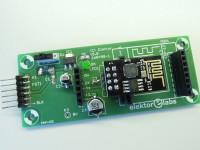
ESP8266/ESP12 programmer [160490-I]

Tool for quick and easy programming!
Designed by P. Rondane
With this PCB and a 3.3V FTDI USB cable you can program all ESP8266/ESP12 modules. Two sockets on the board connect directly to the most common types, while an additional socket can connect to any other, more exotic member of this family. No jumpers or switches are needed to set the module in programming mode. The 3.3V FTDI cable is used to simplify the design and also powers the ESP module during programming.
Electronics
The circuit is powered by the FTDI cable connected to the 6-way pin header K1. The 3.3V low-drop regulator IC1 is needed to lower the 5V VCC supplied by the FTDI cable.
S1 switches the supply voltage for the ESP module and can of course also be used as reset without disconnecting the USB interface. LED1 indicates that the power is switched on.
C4 and C5 are smoothing capacitors for the power supply of the ESP modules.
The modules don’t need special configuration to be switched to programming mode. The PCB wires the ESP8266’s pin GPIO0 to GND and pins RST and CH_PD to 3.3V, the ESP12’s pin EN to VCC and pins GPIO0 and GPIO15 to 0V, so the modules will automatically be set to programming mode after power-on.
Socket K2 provides all signals needed (i.e. 0V, 3.3V, RX and TX) to connect and program any other ESP module to this programming interface.
Although the BOM prescribes a 0805 resistor and 100nF capacitors, the footprints on the PCB also match larger 1206 components.
This PCB makes programming ESP modules very easy, you don’t have to bother about bad contacts or EMC issues you could have when you use a breadboard….
BOM
Resistor
R1 = 220 Ω, thick film, 5%, 0.1W, 150V
Capacitor
C1,C3,C5 = 100 nF, 50 V, X7R, 0805
C2 = 10µF, 16V radial can SMD
C4 = 100µF, 16V radial can SMD
Semiconductor
LED1 = LED, green, 3 mm
D1 = LL4001G 50V, 1A
IC1 = LM3940 3.3V LDO
Other
S1 = slide switch SPDT, Through Hole, (EOZ 1K2 series) 500mA
K1 = Pin header, breakable, 1 row, 6-way, horizontal
K2 = Pin socket breakable, 1 row, 6-way, vertical
MOD1 = 2 x Pin socket for ESP12, breakable, 1 row, 8-way, vertical
MOD2 = Pin socket for ESP8266, breakable, 2 rows, 8-way, vertical


Diskussion (0 Kommentare)