Nixie thermometer/hygrometer wireless sensor [120586]
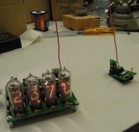
This is an update of the Nixie Thermometer/Hygrometer (110321-I) published in the June 2012 issue of our magazine. In the original design a small SHT21 sensor carrier PCB was connected to the main board via a four wire cable (I2C bus plus power supply lines) . Now this cable is replaced by two small microcontroller boards establishing a wireless link using two RFM modules.
This is an update of the Nixie Thermometer/Hygrometer (110321-I) published in the June 2012 issue of our magazine. In the original design a small SHT21 sensor carrier PCB was connected to the main board via a four wire cable (I2C bus plus power supply lines) . Now this cable is replaced by two small microcontroller boards establishing a wireless link using two RFM modules. The remote PCB carries the sensorboard and is powered by one CR2032 lithium battery.
No modifications of the original boards needed, just plug & play. The pictures show our prototype with the 433MHz version of the RFM12 modules, but also 868MHz and 915MHz versions will be supported.
Since the circuit for the transmitter and receiver are almost identical, only one PCB layout is needed. The shape of the PCB is designed to fit exactly on the corner of the main PCB.
PCB and programmed controllers can be bought at the Elektor shop:
http://www.elektor.nl/search?cat=0&q=120586
Diskussion (2 Kommentare)
Lucky vor 9 Jahren
We also added 6-pin header K2 to the PCB to make in-circuit programming of the PIC16LF1847 possible, the pinning of this connector is identical to the PICkit2 and -3 connector.
Program the microcontroller before you install the RFM module and humidity/temperature sensor (transmitter PCB only), or place these modules in sockets and remove them before programming. Remember that the power supply for both is 3.3V max., you may damage them if you accidentally set your programming interface to 5V instead of 3.3V!
As we mentioned before the RFM12 modules are available in 433, 868 and 915MHz versions and the firmware must support all three frequencies. Every version requires specific initialization, at start up the correct frequency must be written to one of the RFM12's internal registers. We use the RB6 and RB7 pins on the programming interface connector K2 as jumpers to set the frequency of the radio module:
RB6 RB7 frequency
0 0 433MHz
1 0 868MHz
0 1 915MHz
VDD and GND can also be found on this connector, so it’s quite easy to use a SIL socket and solder some wires on its pins to set RB6 and RB7 to the correct logic levels for the RFM12 used. On reset the PIC will read these input pins switch to the correct frequency. And of course: don’t forget to cut the wire antenna length accordingly (approx. 17cm, 8.5cm or 7.8cm for quarter wavelength).
On power up the microcontroller on the battery powered sensor/transmitter module measures the battery voltage and the LED will blink:
1x if > 2.5V
2x if > 2.7V
3x if > 2.9V
arlenm vor 8 Jahren
smithy vor 9 Jahren
Lucky vor 9 Jahren
smithy vor 9 Jahren
Lucky vor 9 Jahren
We also added 6-pin header K2 to the PCB to make in-circuit programming of the PIC16LF1847 possible, the pinning of this connector is identical to the PICkit2 and -3 connector.
Program the microcontroller before you install the RFM module and humidity/temperature sensor (transmitter PCB only), or place these modules in sockets and remove them before programming. Remember that the power supply for both is 3.3V max., you may damage them if you accidentally set your programming interface to 5V instead of 3.3V!
As we mentioned before the RFM12 modules are available in 433, 868 and 915MHz versions and the firmware must support all three frequencies. Every version requires specific initialization, at start up the correct frequency must be written to one of the RFM12's internal registers. We use the RB6 and RB7 pins on the programming interface connector K2 as jumpers to set the frequency of the radio module:
RB6 RB7 frequency
0 0 433MHz
1 0 868MHz
0 1 915MHz
VDD and GND can also be found on this connector, so it’s quite easy to use a SIL socket and solder some wires on its pins to set RB6 and RB7 to the correct logic levels for the RFM12 used. On reset the PIC will read these input pins switch to the correct frequency. And of course: don’t forget to cut the wire antenna length accordingly (approx. 17cm, 8.5cm or 7.8cm for quarter wavelength)