
Pico adjustable power supply and quasi-analog voltmeter
With the development board from the Raspberry Pi Pico Experimenting Kit from Makerfabs, which is offered by Elektor in a bundle, and an additional board with a few components, a simple adjustable power supply can be built for quickly testing small relays, diodes, transistors and even small electronic circuits. The special thing about it is that the voltage that has just been set is shown on the small colour display in a quasi-analogue way, thanks to the microcontroller without relays in three measuring ran
While experimenting with the development board from the above-mentioned kit from Makerfabs, I recently wondered whether it would not be possible to show an analog voltmeter with a pointer on the small colored display, whose rotation from a basic position corresponds to the voltage just measured.
I finally succeeded, as I will show below.
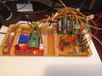
Figure 2 shows a Close-up of Close-up of the the additional circuits for the project, which are located on a 70x 80mm PCB with solder points.
The voltage of the Raspberry Pi Pico at the analog inputs may not exceed approx. 3.3 V. IC2 contains two op-amps, of which act as voltage followers. Without controlling the IC4, IC5 and IC6 optocouplers, the voltage dividers from the resistors R4.. R17, a DC voltage to be measured between X14 and GND from 10V to 2.5 V at X13* before the first operation. If a voltage of 5V is applied between X13 and GND, this is reduced to 2.5V at X13* by R16 and R17. This voltage value is offered to the second op-amp, which passes it on to the analog input ADC2(GP28) of the microcontroller.
In the case of an analogue voltmeter with different measuring ranges, it makes sense to first switch on the largest measuring range in order not to overload the measuring mechanism in the device before selecting the next lower measuring range, if this is possible on the basis of the display. The above-mentioned electronic switching of the measuring ranges of the project presented here is done by a program in MicroPython as follows: DC voltages to be measured are always connected between X14 and GND.
When starting the program, the microcontroller writes the term voltmeter at the top of the color display and first draws 11 red graduation marks of a scale. Their starting points lie on a quarter circle at a distance (radius) of 85 pixels to the axis of the pointer of the quasi-analog voltmeter. Their endpoints are on a quarter circle at a distance (radius) of 90 pixels to the axis of the pointer of the quasi-analog voltmeter to be displayed. This axis has the pixel coordinates X=10 and Y=110. The calculations of the start and end points of the 11 lines is done in the program in MicroPython using the mathematical angular relationships sine and cosine.
When starting the program, the designations 0, 2, 4, 6, 8 and 10 appear in yellow outside the displayed scale for a measuring range of 10V. In addition, the yellow light-emitting diode on the development board is switched on. As in Figure 3, a line with a length of 80 pixels is drawn from the axis mentioned above in green. Their angle to the horizontal position (0 degrees) corresponds to the voltage currently applied for the measurement. In Figure 3, a voltage of 2 V is currently measured. Their value is also shown digitally in the upper right corner of the display, in Figure 3 this is U= 1.98 V If the displayed voltage is 5V or less than 5V, you can switch to the next smaller measuring range. This is done with the help of the IC4 and IC5 optocouplers, whose phototransistors are connected in series and parallel to R14 and R15 in series.
When starting the program, the designations 0, 2, 4, 6, 8 and 10 appear in yellow outside the displayed scale for a measuring range of 10V. In addition, the yellow light-emitting diode on the development board is switched on. As in Figure 3, a line with a length of 80 pixels is drawn from the axis mentioned above in green. Their angle to the horizontal position (0 degrees) corresponds to the voltage currently applied for the measurement. In Figure 3, a voltage of 2 V is currently measured. Their value is also shown digitally in the upper right corner of the display, in Figure 3 this is U= 1.98 V If the displayed voltage is 5V or less than 5V, you can switch to the next smaller measuring range. This is done with the help of the IC4 and IC5 optocouplers, whose phototransistors are connected in series and parallel to R14 and R15 in series.
If the two optocouplers are controlled by a high level at GP6, their two collector-emitter distances become very low impedance and bridge the two resistors R14 and R15. This has the effect that the voltage to be measured is directly connected between X13 and GND. In this case, the label is changed as in Figure 4 outside the red scale lines for a measurement range of 5V. In green, 0, 1, 2, 3, 4 and 5 now appear. The green light-emitting diode is switched on instead of the yellow one.
Optocopller IC6 acts in a similar way with the collector-emitter link of its phototransistor. It is controlled by a high level on GP7. If the DC voltage to be measured is 2.5 V or less, the Pico can control GP6 and GP7 and thus practically connect X14 with X13*. In Figure 5, the smallest measuring range is switched on. The labels outside the red scale lines were corrected by the microcontroller accordingly in 0, 0.5, 1, 1.5 and 2.5, and now appear in blue color on the display. In addition, the blue light-emitting diode is now switched on.
The Raspberry Pi Pico in this project measures the voltage on the potentiometer from the aforementioned kit and transmits its value to a small board with a serial digital-to-analog converter MCP4725. Its output voltage of 0.. 3.3 V is offered to an LM358 as in Figure 2 IC1, which amplifies it to a voltage of 0..10 V and offers it to its second OP, which serves as a voltage follower here. At its output, therefore, a DC voltage source with an output voltage of 0.. 10 V is available that can be adjusted by means of a potentiometer. According to the information in the manufacturer's data sheets, the LM358 IC can be loaded up to about 20 mA.
On the 70 x 80 mm PCB with solder dots, there is also a voltage regulator 78L05 that provides a fixed voltage of 5 V. A resistor of 1 ohm is connected between the non-inverting input of op-amp 1 in IC3(LM358) at the bottom right of Fig. 2 and GND. If, for example, a light-emitting diode is connected via a series resistor of 1 kiloohm between +5V and GND*, its current causes a small voltage drop in the resistance of 1 ohm. This low voltage is amplified a hundredfold with the help of R10 and R11 in Op1 and offered to OP1 in IC3, which serves as a voltage follower. 1 milliampere (1 millivolt) leads to 0.1 volts and 10 milliamperes (10 millivolts) lead to 1 volt at the output of OP2. This voltage, which is a measure of the current in the resistance of 1 ohm, can also be measured with the quasi-analog voltmeter of this project. On the board with solder points there is also a micro button, which is connected between the pico pin RUN and GND and serves as a reset button. A light-emitting diode serves as an indication of the series connection of a battery of 9V with another of 4.5V. Buttons 1, 2 and 3 of the development board are connected to a two-pin header via insulated flexible cables, one side of which is connected to GND. This allows one of the three possible measuring ranges of the quasi-analogue voltmeter to be set with the help of a jumper.
Figure 6 shows a display of the quasi-analog voltmeter with that of a connected digital multimeter in the voltage measurement range for comparison.
Figure 7 shows a red light-emitting diode, which is connected via a series resistor of 1 kiloohm between +5 volts and GND. The voltage on it is displayed on the quasi-analogue voltmeter in the measuring range 5V.
Figure 8 shows a red light-emitting diode connected via a series resistor of 1 kiloohm between +5 V on the PCB with 70x80mm solder points and the collector of an NPN transistor BC547B. Its base is connected to the adjustable DC voltage source presented above via a resistor of 10 kiloohms. With the potentiometer from the above-mentioned kit from Makerfabs, their output voltage is increased until the transistor steers through and the light-emitting diode begins to glow. The voltage achieved at the base is shown on the small colour display in the measuring range 5 V quasi-analogue and digitally at the top right.By reconnecting the insulated flexible cable to the X14 switching point, other partial voltages of the small electronic circuit can be measured. If the circuit point GND* is used instead of connector GND, the total current consumption of the circuit can be measured indirectly, as explained above.
Summary, Outlook
In the post above, I showed that the development board from Makerfabs' Raspberry Pi Pico Experimenting Kit, which is offered by Elektor in a bundle, with the microcontroller on it, can very well be part of a simple adjustable power supply for quickly testing small relays, diodes, transistors, and also simple electronic circuits. The necessary additional electronic circuits are located on a 70 x 80mm printed circuit board with solder points. On the small colored display of the development board, a scale with 11 graduation marks is displayed, which, depending on the measuring range, is labeled in color on the outside to match the currently switched on light-emitting diode on the development board. When a measuring voltage is applied, its value is displayed digitally and also quasi analogue by the Raspberry Pi Pico in the upper right corner as a simulated pointer, whose angle to the horizontal position corresponds to the voltage value just measured, in three electronically switchable measuring ranges. As voltage sources for the additional circuits in the project presented above, the series connection of a 9V battery and a 4.5V battery is sufficient. For currents larger than 20 mA, a power op-amp can be connected to the output of IC1(LM358). In this case, however, a power supply with a stable output voltage of 12 V is required instead of the batteries.
For the additional circuits on the 70x80mm PCB, to use a program that can be used to develop layouts for PCBs. a circuit board can be designed. The measuring range of the quasi-analog voltmeter can be extended in a similar way to what has been presented above. There are other possible applications for the project presented above, for example to display the temperature and humidity quasi-analog with the DHT11 sensor module from the kit, switchable using the buttons on the development board. The project presented above was born out of the joy of experimenting and programming the Raspberry Pi Pico in MicroPython.It's not perfect, and neither is the program I developed for it. Perhaps my contribution can encourage other readers to program a Raspberry Pi Pico in MicroPython.
Notes on the construction and testing of the additional circuits on the 70x80mm PCB
I would first place the two-pin socket strips with the help of the illustrations to the article, which were made with the program Lochmaster4.0, and solder them on copper side. The IC sockets can be placed and soldered onto them.
The connections of pins 1 with pins 5 of IC1, IC2 and IC3 are made on the copper side of the PCB with short pieces of wire, The capacitors of 100nF between pins 8 and 4 of IC1, IC2 and IC3 can also be soldered on the copper side of the PCB. Several connecting cables can also be soldered on the copper side.
Small circuit boards with a MCP4725 are offered on the Internet by various dealers. If such a board is available that has a pin header, a socket strip and a five-pin socket header must also be soldered in at the top of the circuit board. This is used to connect the serial digital-to-analog converter to the pins of the Raspberry Pi Pico on the board of the development board.
Please note the following:
The pins of an existing small board with a MCP4725 may have a different order than the one I have, for which I created the files with the software Lochmaster4.0.
Now the connecting cables between the IC sockets can be soldered on. The resistors and the trim potentiometers and the corresponding connecting cables are to be soldered to them. I recommend checking again and again after the individual soldering processes with a multimeter in the resistance measurement range whether the individual connections have been successful, or whether short circuits with solder have been accidentally caused. In the first case, this means soldering at the relevant point and in the second case, the connection accidentally caused by solder must be interrupted. The series resistors R14, R15, R16 and R17 in front of pin 3 of the IC2 are to be soldered in upright.
A digital multimeter, which has a resistance measurement range of 10 megaohms, can be used to check whether this has been successful. In this case, a resistance of 4 megaohms is to be measured between circuit pointX14 and GND, a resistance of 2 megaohms between circuit pointX13 and GND and a resistance of 1 megaohm between circuit pointX13* and GND. If the voltage regulator with its two capacitors at the input and output and the light-emitting diode with its resistor have also been soldered in, and the socket headers with the pin header for the jumper have been connected correctly, a 9V battery can be connected to the respective sockets at the top right of the PCB and a jumper can be plugged in. The light-emitting diode should now light up. Between the output of the voltage regulator and all points connected to GND, it should be possible to measure a voltage of 5 V with a digital multimeter.
Then the existing measuring device can be used to check whether the voltage of the connected 9V battery can also be measured between the pins 8 of the sockets for IC1, IC2 and IC3 and the circuit points GND of the printed circuit board. Now the voltage source is disconnected from the circuits on the circuit board again. Then all connecting cables to the IC socket for the mounting of the three PC817 optocouplers with the respective resistors must be soldered and then checked with a multimeter in the resistor range whether this has been achieved without error. Then the micro button, which serves as a reset button when operating the circuits with the Raspberry Pi Pico, and the two-row three-pin header in conjunction with its three-pin socket header must be soldered correctly according to the illustrations of Lochmaster4.0.
After re-checking these subcircuits in the resistance range of a digital multimeter, the circuits on the PCB can be connected to the respective pins of the Raspberry Pi Pico on the development board using flexible insulated wires according to the specifications in the schematic.
Please note that this will initially be done without flexible insulated connecting cables to pin GP28 (ADC2), GP6 and GP7!
If the potentiometer from the Makerfabs kit is correctly connected to the development board from it, the MicroPython program can now be started in Thonny, after a small circuit board has been connected to the ICMCP4725 on the 70x80mm circuit board. Immediately after starting the program, the term voltmeter is shown on the small colored display at the top, and as can be seen in the pictures of the article, 11 tick marks of a scale appear in red color and the designations 0, 2, 4, 6, 8 and 10 in yellow color. A digital multimeter is connected to the output terminal of the MCP4725 and this is set to voltage measurements.
If the sliding contact of the potentiometer is moved from the initial position to the end position, the voltage on MCP4725-OUT should change from 0 to about 3.3 V. If this succeeds, IC1, IC2 and IC3 can be inserted into their sockets. Now the power supply of the 70x80 mm PCB can be switched on by a 9V battery series to a 4.5V battery with the help of the jumper in question. The output voltage of the MCP4725 is amplified in IC1. This can be measured between circuit point U_out1 and GND. When the potentiometer is in the end position, the R13 trim potentiometer can be adjusted with the help of a screwdriver so that the output voltage of IC2 is 10 volts. If circuit point U_out1 is now connected to X14 with the help of a flexible insulated cable, a voltage of 2.5 V must be measured between X13* and GND if the soldering work has been carried out correctly beforehand.
Once the three optocouplers have been correctly plugged into the IC socket provided for this purpose, their function can now also be checked. If you connect the pin intended for connection to GP6 of the Raspberry Pi Pico on the 70x80mm PCB with solder points with the output of the voltage regulator (+5V), so that a voltage of 5 V is now measured between X13* and GND. If you also connect the circuit point, which is to be connected to GP7 of the microcontroller later in operation, a voltage of 10 V is now measured between the ADC2 connector of the IC2 and GND. If this test has been carried out successfully, it can be assumed that the three optocouplers IC4, IC5 and IC6 are working properly. The connecting lines to a point +5V of the voltage regulator have to be interrupted again and the two lines to GP6 and GP7 of the microcontroller can be reconnected.
To properly adjust the gain of the op-amp1 in IC3, a light-emitting diode is connected via a series resistor of 1 kiloohm between the output of the IC1 and GND*, in such a way that the anode of the LED is connected to +5V and its cathode is connected to GND* via the resistor. When the grinder is in the end position, the light-emitting diode now has a resistance of 1 kiloohm between +10 V and GND*. According to Ohm's law, the voltage at the resistor in volts corresponds to the current in the resistor in milliamperes. This should be a voltage of almost 8 volts. If you measure the voltage between the output of IC3 and GND, then this voltage should be about 0.8 V. The exact value can be set with the help of a small screwdriver on the R10 trim potentiometer.
If the output voltage of IC2 was a maximum of 2.5 V in the tests described above, this circuit point on the 70x80mm PCB can be connected to the GP28 pin (ADC2) of the microcontroller by means of a flexible insulated cable. The simple, adjustable power supply controlled by the Raspberry Pi Pico can then be put into operation.
Unfortunately, there is an error in the circuit diagram in the designations at the top right of the information on how to connect a MCP4725.
Please note the following: PICo_SCL is to be connected to GP9 and Pico_SDA to GP8 of the Pico!
Extension of the circuits of the project and of the program in MicroPython.
The project now offers the four voltage measurement ranges 20 V, 10 V, 5 V, and 2.5 V In addition, instead of the voltage, the current flowing in the consumer to be tested up to 100mA is now digitally displayed in the upper right of the display.
After a measuring range expansion to 20 V, four voltage measuring areas are now available, namely 20V, 10V, 5 V and 2.5V. The original circuit of the voltage division in front of the entrance of the first operating amplifier (PIN3) in IC2 was supplemented by four resistances in row circuit of 1 megaohm between pin X14 and the now new PIN X15. Megaohm between X15 and X14, two megaohm between X14 and X13 or a megaohm between X13 and X13*. In this way, the respective measuring range can be set using a jumper.
It is possible, as can be seen on the current circuit diagram, to connect a performance operating amplifier L272M to the output U_Out1 from IC1.
For this purpose, U_out1 is connected to the non-inverting input of one of the op-amps in IC8. Between its output U_out1_P and GND*, a consumer to be tested can be connected. Since IC8 gets very warm during operation, it carries a heat sink.
IC8 and the other operating amplifiers are now also operated at 18 V. To do this, I use a battery of twelve in series connected rechargeable batteries(AA Capacity:2.550mWh). These are located in two battery holders for six cells of 1.5 V.
This makes it possible for me to test components with larger streams than 20 mA.
In this version, the four voltage measurement areas 20V, 10V, 5V and 2.5 V can be selected with a jumper. Instead of the digital display of the measured voltage at the top right of the display, the current is displayed up to a value of 100mA.
If R15 with 1 ohm is connected in parallel with the jumper to R13, the indirectly measured current can be even greater than 100mA. The program in MicroPython must then be adapted accordingly to the lines in question.
Please note the following: To set this measurement range for the current Connector ADC1 must not be connected to ADC1 on the Raspberry Pi Pico (pin 27) first, so as not to damage the microcontroller at the analog input ADC1 by too high an input voltage!
To set such a large stream, I first concluded a digital multimeter parallel to the resistance R13, i.e. between the connection GND* and GND. Then I put six yellow LEDs on a breadboard via a resistance of 470 ohms and connected them all to the output Out1 of the L272M and GND*. According to the Ohm's law, the overall current of the LEDs could be indirectly measured with the voltmeter parallel to R13.
Then when the program in Micropython was running, with the potentiometer from the KIT of MakerFabs, I increased the tension on the LEDs to such an extent that just 50 MilliVolt could be measured on R13.
I adapted the setting of the trim potentiometer R5 with a small screwdriver when the potentiometer was adjusted from the kit of MakerFabs until the tension at the ADC1 output from IC3 1 volt was.
Only now could I connect the output ADC1 to IC3 to the PICO analogue ADC1 input. The program in Micropython was supplemented in the main area by reading ADC1.
At the point of the digital representation of the voltage in the top right on the display, the current is displayed up to a value of 50mA.
The current to be measured is adjusted with a screwdriver on the R5 trim potentiometer. The voltage at R13 and the voltage at the ADC1 output of IC3 are measured alternately with a digital multimeter.
Please note the following: The original circuits I developed to the post and also the additions presented here are not perfect.
When the optocouplers are activated, the collector-emitter resistors of their phototransistors do not bridge the resistances of four, two, or megaohms perfectly like a switch with a resistance of less than one ohm.
The megaohm resistors used are metal film resistors, but have tolerances like the other components of my project. The op-amps used have Input Offset Voltage Values and the microcontroller's ADC also has tolerances.
The program in Micropython is not perfect and can certainly be improved.
Nevertheless, I think that the accuracy of the measurements with the simple project presented here is sufficient for the hobby sector.
Updates vom Autor