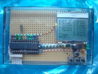
Quick development

A lot of projects are small and build only once. Building a pcb with a uC and some IO in a casing can take less than an hour.
To begin with the end : almost all my projects fit into the casing of an audio cassette.
As a bonus they are easy to stack, and that count if you have more than a dozen.
Next, I allways use prototyping boards H25PS200 (or H25PS160) triple dot chain (it's also available in epoxy, but a little more expensive). It has more advantages than isolated or striped prototyping boards and moreover you can position almost every PDIP IC on it and have a free connection ready for every pin. I cut the boards to about 65 mm and that fits nicely into the casing. I have a drawing of the holes as an aid when it becomes complicated to position the components. Smd components can be used too. I regularly use SOIC and SO-8, sometimes with some fiddling. I rarely use wires on the copper side. There are examples in the attachments.
With some experience and knowing the matrix it's sometimes even possible to follow the schematic without looking at the copper side. Try that with any other method or a dedicated pcb. To facilitate that I use multiple color wiring. Using smd's makes that part more difficult though.
As an example look at the "Xmas" project. The copper side is presented in the attachments, as some details for smd's, and several other examples. Note that I use a flat SPI connector, but that was just my choice many years ago and I stick to it.
When there is only one button, I use a button with a 9 mm shaft that can be activated by just pressing the case (again in the Xmas project). Note : the zif and the audio project are not finished, just examples.
The Am328... shows my implementation of some Arduino-like board which I use with some "shields".


Diskussion (0 Kommentare)