
STM32 mini PLC
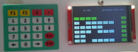
Mini PLC ideal for model trains and small hobby (automation) projects. Update now with 4 analog inputs
STM32F407VGT6 Discovery board
Easy to program
Ideal for model building or other hobby applications
Cheap
16 digital inputs
16 digital outputs
can be expanded to:
64 digital inputs
64 digital outputs
4 analog inputs
4 analog inputs
possible comparisons
AI = equal to
AI > greater than
AI < less than
AI >< greater than and less than
4 PWM outputs (hardware PWMs do not take up processor time)
frequency can be set per PWM
PWM outputs can be controlled by an analog input, for example to control a speed control by a potentiometer.
PWM outputs can be controlled by an analog input, for example to control a speed control by a potentiometer.
Use the PWM_F command for this.
64 internal markers
64 internal counters
counter_up input
counter_down input
counter_reset input
counter_up output 1 if count value reached
counter_up output 1 if count value reached
counter_down output 1 if count value 0
64 internal timers
timer input
timer_reset input
timer_output 1 if set time reached
adjustable between 0.1 second and 99:59:59:90
TMR56 to TMR63 continuous timers
deliver square wave of set time if input 1
Due to the limited dimensions of the screen, programming can only be done using Arduino logic
&& AND
|| OR
^ XOR
! NOT
(
)
/\ RISING EDGE
\/ FALLING EDGE
=
SET
RST
Cycle time adjustable between 10 milliseconds and 100 milliseconds (hardware timer interrupt)
To keep the Timer seconds the same as real seconds set to:
10 milliseconden
20 milliseconden
25 milliseconden
50 milliseconden
100 milliseconden
Program can be saved in the FLASH memory of the STM32F407.
16000 bytes of freely programmable memory
Maximum 1000 lines.
The number of lines and the cycle time are determined by the number of bytes per line.
Each program line can be a maximum of 20 bytes long (screen size and RAM storage capacity limitation)
with maximum usage of bytes in each line, the maximum number of lines is 800.
bytes per instruction :
1 byte
&& || ^ ! = SET RST ( ) /\ \/
2 bytes
INxx OUTxx Mxx TMRxx CTRUxx CTRDxx TMR_Rxx CTR_Rxx
3 bytes
AI = x %%% AI nummer instel percentage
AI > x %%% AI nummer instel percentage
AI < x %%% AI nummer instel percentage
PWM x %% % PWM nummer procent uitsturing
PWM_F x x PWM_F nummer nummer van analoge ingang die PWMx stuurt
4 bytes
4 bytes
AI >< x %%% %%% AI nummer instel percentage > instel percentage <
Required cycle time depends on the number of selected inputs/outputs and program length
time required for 16 inputs/outputs without program
331 microseconden
time required for 64 inputs/outputs without program
659 microseconden
average time per instruction
1.5 microseconden
For full use of the program space with 64 inputs/outputs, 50 milliseconds should be more than sufficient.
659 microseconden + (16000 instructies * 1.5 microseconden) = 24659 microseconden.
Analog and digital inputs are read at the beginning of the program
Digital outputs and PWMs are calculated during the runtime of the program but only written to the outputs at the end of the program.
Program line processing without brackets is done from left to right.
Program line processing with brackets, first all logic within the brackets from left to right until all brackets are processed and then the entire line from left to right.
Automatic restart of the program if saved in FLASH and prog/run switch set to run.
a program example
a program example
0000 IN 0 = OUT 0
0001 IN 0 = TMR 56
0002 TMR 56 = OUT 1
0003 IN 0 && ! TMR 56 = OUT 2
0004 TMR 56 = CTRU 0
0005 CTRU 0 && TMR 56 = CTRU 1
0006 CTRU 0 = OUT 3
0007 CTRU 1 = OUT 4
0008 /\ CTRU 1 = CTR_R 0
0009 /\ CTRU 0 = CTR_R 1
0010 AI >< 0 10 50 = OUT 5
0011 IN 0 = PWM_F 0 0
0012 AI > 0 25 = PWM 1 25
0013 ! OUT 6 = OUT 6
Updates vom Autor