
☎ Vintage phone 4G Full Options
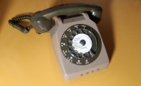
Do you like vintage objects, but you don't want to give up modernity? This project transforms an old rotary dial phone into a real 4G mobile phone thanks to an ATmega328 and a BK A7670E GSM module. Objective: Give a second life to a wired phone while keeping the experience of a good old rotary dial! A functional 4G phone, capable of dialing numbers, and making calls, while maintaining the aesthetics and pleasure of using a retro phone. For now, only to make calls, but I continue to move forward to offer the
- Microcontroller: ATmega328 (Arduino-UNO_NANO)
- GSM 4G module: BK A7670E, equipped with the interface seen here: https://www.elektormagazine.fr/labs/interface-pcb-pour-remplacer-le-sim800-par-un-bk-a7670e
- Picking up and hanging up: Detection of the handset state via the handset switch.
- Dialing: Detection of the rotary dial pulses.
- Audio: Use of the original handset (replacement of the speaker and microphone with a set from a "H.S." smartphone)
- Power supply: 5VDC or option:
- Transportable: 12V equipped with a backup power supply seen here: https://www.elektormagazine.fr/labs/backup-power-supply-project-for-sms-gps-alarm-4g-module
- Indicators: Debug LED (picked up/hung up), 4 LEDs displaying the dialed numbers converted to binary
Functions of the version with 3-letter library for a number in the directory:
- Call to any authorized number (the FR version only allows 06 and 07)
- Abbreviated numbers with letters from the dialer for favorite contacts (put in 'Library')
- The object works on battery using "Backup-Battery-for-Tracker" see subject
- Use the "Level Convert" card see subject
- Buzzer, vibrator, debug LED and bin display LED are optional, but it helps -:)
- Receive external call if in directory memory!.
We refuse incoming calls that are not registered in the directory ::
see vintage_phone library
We systematically delete received SMS.
We accept calls from the directory,
When we receive a call, if the caller is registered in the directory, launches a timer, writes in binary the number on bin LEDs, the place of the calling number.
From 1 to 15 numbers (only 4 bin leds...)
(Possible to have more numbers, or to authorize all incoming calls....
No answer to the call, reset incoming call, bin leds and ring detection
Detection of the handset picked up
A mechanical switch (present in the phone) detects the handset picked up/on hook.
Connected to the PD3 input (D3) with interruption (INT1) which is declared with an EXTERNAL pull_up.
On hook, switch open, pull_up D3, HIGH
On hook, bring GND to D3, LOW
Activate PB5 (debug led)
Dialing the number
Reading the rotary dial
A mechanical switch (present in the dial) detects the rotation of the dial
connected to D4 INTERNAL pull_up
The dial generates a series of pulses corresponding to the number (eg: 1 → 1 pulse, 0 -> 10 pulses).
These pulses are read on an input with PD2_INT0 interruption if the handset is picked up (PD3_INT1).
At rest, the pulse switch is at GND = LOW.
When pulses are generated, we go to the HIGH state via the EXTERNAL pull_Up.
The duty cycle of the pulses is 64% HIGH, 36% LOW
A counter variable stores the number of pulses.
We check, if we do not start with a 0, as soon as there are three digits if abbreviated number.
Abbreviated numbers must not start with a 0 (letter O and Q prohibited on first digit)
Number Ok, we launch the call, otherwise...
At the end of the rotation, the digit is added in a table char num[10]
The number is ok, we launch the call.
Buzzer tone ok
If error, buzzer tone error
See schema and jpg
Lien vidéo
https://youtu.be/eXsS7FtJ0Qc
https://youtu.be/PlSb3yJ2O-Y
https://youtube.com/shorts/JrVy3nhKHqM
The sounds come from this site ::
https://lasonotheque.org/
other info here :
http://jacques.reumont.free.fr/
//FR
Caractéristiques techniques
- Microcontrôleur : ATmega328 (Arduino-UNO_NANO)
- Module GSM 4G : BK A7670E, équipé de l'interface vue ici : https://www.elektormagazine.fr/labs/interface-pcb-pour-remplacer-le-sim800-par-un-bk-a7670e
- Décrochage et raccrochage : Détection de l'état du combiné via le commutateur du combiné.
- Numérotation : Détection des impulsions du cadran rotatif.
- Audio : Utilisation du combiné d'origine (remplacement du haut-parleur et du micro par un ensemble issu d'un smartphone "H.S.")
- Alimentation : 5VDC ou option :
-Transportable : 12V équipé d'une alimentation de secours vue ici : https://www.elektormagazine.fr/labs/backup-power-supply-project-for-sms-gps-alarm-4g-module
- Indicateurs : LED de débogage (décroché/raccroché), 4 LEDS affichant les numéros composés convertis en binaire
Fonctions version avec librairie 3 lettres pour un numéro en répertoire :
- Appel vers n'importe quel numéro autorisé (la version FR autorise uniquement le 06 et le 07)
- Numéros abrégés avec lettres du cadrant pour les contacts favoris (mis en 'Librairie')
- L'objet fonctionne sur batterie en utilisant "Batterie-de-Secours-pour-Tracker" voir sujet
- Utilise la carte "Level Convert" voir sujet
- Buzzer, vibreur, Led de debug et Led affichage bin sont optionnelles, mais cela aide -:)
- Recevoir appel extérieure si en mémoire du répertoire !.
On refuse les appels entrants qui ne sont pas inscrit dans le répertoire ::
voir librairie vintage_phone
On efface systématiquement les SMS reçus.
On accepte les appels du répertoire,
Lorsque l'on reçoit un appel, si l'appelant est inscrit dans le répertoire, lance une temporisation, écrit en binaire le chiffre sur Leds bin, la place du numéro appelant.
De 1 à 15 numéros (seulement 4 leds bin...)
(Possible d'avoir plus de numéro, ou d'autoriser tous les entrants ....
Pas de réponse à l'appel, reset appel entrant, Leds bin et détection de sonnerie
Détection du combiné décroché
Un switch mécanique (présent dans le téléphone) détecte le combine décroché/raccroché.
Raccordé sur l'entrée PD3 (D3) avec interruption (INT1) qui est déclarée avec un pull_up EXTERNE.
Raccroché, switch ouvert, pull_up D3, HIGH
Décroché, amène GND sur D3, LOW
Active PB5 (led debugg)
Composition du numéro
Lecture du cadran rotatif
Un switch mécanique (présent dans le cadran) détecte la rotation du cadran
raccordé sur D4 pull_up INTERNE
Le cadran génère une série d’impulsions correspondant au chiffre (ex: 1 → 1 impulsion, 0 -> 10 impulsions).
Ces impulsions sont lues sur une entrée avec interruption PD2_INT0 si le combiné est décroché (PD3_INT1).
Au repos, le switch impulsion est à GND = LOW.
Lorsque des impulsions sont générées, on passe à l'état HAUT via le pull_Up EXTERNE.
Le rapport cyclique des impulsions est de 64% HIGH, 36% LOW
Une variable compteur stocke le nombre d’impulsions.
On vérifie, si on ne commence pas par un 0, dès qu'il y a trois chiffres si numéro abrégé.
Les numéros abrégés ne doivent pas commencer par un 0 (lettre O et Q interdite sur premier chiffre)
Numéro Ok, on lance l'appel, sinon...
À la fin de la rotation, le chiffre est ajouté dans un tableau char num[10]
Le num est ok, on lance l'appel.
Buzzer tone ok
Si erreur, buzzer tone error
Voir schéma et images
Lien vidéo
https://youtu.be/eXsS7FtJ0Qc
https://youtu.be/PlSb3yJ2O-Y
https://youtube.com/shorts/JrVy3nhKHqM
Les sons proviennent de ce site ::
https://lasonotheque.org/
Un site tout plein de bonnes infos ici :
http://jacques.reumont.free.fr/
Bruno Clerc
Le 10/03/2025
Updates vom Autor