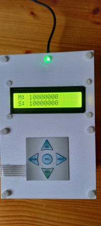
AD9851 with frequency correction versus GPS time base

AD9851 controlled by a STM32F103C8, delivers the requested frequency calibrated vs a GPS timebase
The requested frequency is the delivered frequency.
High precision frequency: continuously calibrated against GPS time base
Adjustable from 1Hz to 25MHz.
Easy to operate.
How does it work :
GPS module is programmed by the program to send out a pulse of 1Hz or 0.5Hz.
If GPS is not yet connected with satellites 1Hz >> red LED lights up.
If GPS connection with satellites 0.5Hz >> green LED lights up.
GPS pulse is connected to input 74HC08 and input STM32F103C8.
The square wave from AD9851 is converted to a 3.3V signal using a 1N4001 and 1 port 74AHC125.
This 3.3V square wave goes to 1 input of a 74HC08 AND gate.
The other input of the 74HC08 is controlled by the pulse from the GPS module.
The output of the 74HC08 goes to the Timer1 input of the STM32F103C8.
In the STM32F103C8, Timer1, Timer2 and Timer3 are placed in series.
Due to the combination of GPS pulse and square wave from AD9851, the pulses can only be counted if the GPS pulse is high.
With a falling edge of the GPS pulse, the values of the Timers are read in and the Timers are reset.
The number of pulses per second is calculated from the values of the timers and sent to the display.
The read-in frequency is compared with the requested frequency and adjusted if necessary.
If GPS is connected to satellites this should provide a fairly accurate frequency.
The desired frequency can easily be entered using the keyboard.
The setpoint (S:) and the measurement (M:) are shown on the display.
Since the accuracy is determined by whether or not the GPS module is connected, this is displayed by a 3-color LED, only 2 colors are used.
GREEN GPS module connection to satellites.
RED GPS module not connected to satellites.
I do not have the necessary equipment to measure precision.
Anyone with the necessary equipment who finds this a useful application to recreate can always let us know.
Program and documentation on github
https://github.com/thieu-b55/AD9851-automatic-frequency-correction-vs-GPS-timebase


Diskussion (0 Kommentare)