
6-digit Nixie clock [150189, 180588]
This is a remake of the Simple Nixieclock (140013-1). After this project was published we got a lot of questions from our readers about changing the time zone, which was fixed to GMT+1 in the original design but could be altered in the source code of the PIC microcontroller.
Update March 6, 2025
Due to a software issue concerning automatic daylight saving time (DST), the clock started showing zeroes at the beginning of January 2025. This is because the clock's DST database ends at 2025. Several fixes have been proposed in the comments below. To hopefully solve this issue for once and for all, new software was written that does not try to be clever. DST is manual only. Furthermore, it is open-source plain C without funky libraries, so it should be easy to correct and adapt. It is available in the download section below, under the Software tab.
Developed with MPlab-X IDE v6.20 with free C compiler XC8 v3.0.0. A HEX file is included too.
This project should also be easy to adapt for the 4-digit version of this clock (140013-1, see this project).
Rant
Please remember the Y2K bug. If you weren't born yet, look it up. Don't create software that will stop working 30 or more years from now because you implemented some clever function, and you didn't expect the software to last for so long. Please, please, always try to make your work future-proof.
Usage
The new software is simply clock software. It shows the time and that's it. No clever features, no alarms, just the time. If I didn't make dumb mistakes, with this software, the clock will work as long as the GPS will work (and even beyond but with less precision).
Daylight Saving Time (DST, +1 hour) is manual, activate or deactivate it by pressing S1.
When the clock is switched on, it will first test all the digits, then show the time zone (as minutes, 0 to 37) and if “+1-hour” DST mode is activated or not (as seconds, 1 or 0). It can take a long time before the GPS resynchronizes, but you probably have a good spot for the clock with a clear view of the sky. If the GPS drops out, the clock will continue on its internal clock. When the GPS comes back, the clock resynchronizes.
The LED shows if the GPS string has a valid year (i.e. >= 2025, this will work until 2100 because the RMC string does not include the '20' of 2025 [WTF]). When it does, the GPS is outputting stable time data. The time can be good, even if the year is still wrong. Anyway, it is not used by the software other than for showing status information.
The left neon light flashes for every successfully decoded GPS string (RMC). If GPS reception is good, it should flash every second (can vary). The right neon light flashes once per second of the internal clock (stable). The two neon lights are not synchronized.
Keeping S1 pressed while switching on the clock allows setting the time zone (0 to 37; default is 15: GMT+0). Press S1 repeatedly to do so. The value is stored in EEPROM. When S1 is not pressed for 10 seconds, the clock will enter clock mode.
Pressing S1 while the clock is running toggles between +1 hour (DST) or +0 hour (not DST). The value is stored in EEPROM. Default is off.
JP1 selects display of leading hour zero or not.
Original Project Starts Here
This is a remake of the Simple Nixieclock (140013-1, see this project). After this project was published we got a lot of questions from our readers about changing the time zone, which was fixed to GMT+1 in the original design but could be altered in the source code of the PIC microcontroller. The author finally changed the firmware to set the time zone using a switch after reset.
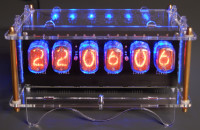
We mentioned in the article that seconds were also counted but not displayed (after all: there were only four digits) and some readers were wondering if the design could be changed to show seconds as well. The PIC18F2480 doesn’t have enough I/O-pins for two extra digits and is replaced by a 40-pin DIP 18F4420. Apart from the two extra 74141’s, Nixie tubes plus an extra neon bulb for separating minutes and seconds digits, there are hardly any changes in the schematic, but of course the PCB layout needed to be redesigned. In the old design we used Russian IN-14 Nixies, but apparently even Ebay-shops in Eastern Europe are running out of stock. The prices have increased dramatically, making these tubes less suitable for new projects. We discussed this with Jan Wuesten, owner of the German tube-webshop www.fragjanzuerst.de (i.e. Ask Jan First), and decided to use IN-12 nixies in this design, which are pin compatible with other oval shaped nixie tubes like the ZM1100 and CD56. Since these are top view nixies, we made a separate PCB for the display that can be mounted perpendicular to another PCB containing the rest of the hardware. Six 10-way (box) headers (spaced on a 100mil grid) are used for the connection between the two boards, making it relatively easy to make your own display on vero board if you want to use other types of nixie tubes.
Updates des Autors