Understanding the Advantages and Disadvantages of Linear Regulators
über

Contributed By Electronic Products
2012-05-08
Despite the popularity of switching DC/DC converters, linear regulators still form a healthy percentage of the business of leading power module chip suppliers such as Maxim, Texas Instruments, Linear Technology, and austriamicrosystems. Modern design techniques and wafer fabrication processes have enabled linear regulators to remain the best choice for a number of applications.
This article compares linear and switching regulators and considers which applications could benefit most from the key advantages of the former, including their simplicity, low cost, and ability to provide stable voltages without the ripples inherent to switching converters.
Avoiding weaknesses
Switching regulators are highly efficient and able to step up (boost), step down (buck), and invert voltages with ease. Contemporary modular chips are compact, reliable, and available from multiple suppliers. Why is there a need for an alternative? The answer is because switching regulators have some weaknesses.
First, they are complex chips and, consequently, it can take a lot of design effort to get a new product working properly. Second, the level of integration of contemporary switching regulators doesn’t come cheaply and increases the chip size. Finally, all that high-frequency switching tends to be noisy.
Voltage and current ripple at the input and output filters, generated by high-frequency operation, can be a major issue for a design using a switching regulator. And while the problems can be tackled, it takes time and design skill to do so.
Linear regulators address all the key weaknesses of the switching type. They are simple (requiring simpler support circuits with fewer external components), cheap, and there is no switching to generate excess noise. In the right application, these modest devices can be a good choice.
| Linear | Switching | |
| Function | Only steps down (buck) so input voltage must be greater than output voltage | Step up (boost), step down (buck), inverts |
| Efficiency | Low to medium, but actual battery life depends on load current and battery voltage over time. Efficiency is high if difference between input and output voltages is small | High, except at very low load currents (μA), where switch-mode quiescent current (IQ) is usually higher |
| Waste heat | High, if average load and/or input to output voltage difference are high | Low, as components usually run cool for power levels below 10 W |
| Complexity | Low, usually requiring only the regulator and low-value bypass capacitors | Medium to high, usually requiring inductor, diode, and filter caps in addition to the IC; for high-power circuits, external FETs are needed |
| Size | Small to medium in portable designs, but may be larger if heatsinking is needed | Larger than linear at low power, but smaller at power levels for which linear requires a heat sink |
| Total cost | Low | Medium to high, largely due to external components |
| Ripple/Noise | Low; no ripple, low noise, better noise rejection | Medium to high, due to ripple at switching rate |
Table 1: Comparison of the characteristics of switching and linear regulators.
Buck operation only
The key phrase in the last paragraph was “the right application,” because linear regulators bring some compromises that mean they won’t work in many designs.
For instance, linear regulators can only step down the input voltage. That might mean boosting the supply voltage by adding batteries to make sure it’s high enough to exceed the voltage required by the silicon. That could mean using five cells with a nominal voltage of 1 to 1.5 V to ensure a reliable 5 V output for the full discharge cycle of the batteries. Adding more cells can soon add up such that their cost outweighs a more expensive switching regulator that can run from fewer batteries. And, of course, the extra batteries take up valuable space.
Moreover, the inability of a linear regulator to boost a voltage is a problem when one component in a product demands a higher voltage than all the others, for example, a display. Similarly, when some analog circuitry requires a negative voltage, the linear regulator can’t be used because of its inability to invert the positive supply.
A linear regulator isn’t as efficient as a switching device, so batteries won’t last as long. Worse yet, even if the batteries still have some charge, but their combined output is below the minimum voltage demanded by the silicon, there will be no way of extracting the remaining charge. In contrast, a switching device can flip to boost mode to drain the last of the power.
In very low-power applications a reduction in battery life may be acceptable to save on the expense of a switching regulator. For example, a consumer is unlikely to be happy if the battery life for a high-power demand product slips from 12 hours to 8 hours because of the use of a linear regulator, but may well be prepared to accept a reduction in battery life from 6 to 5 months for a low-power demand product in exchange for a cheaper purchase price.
Efficiency
Linear regulators may not have the overall efficiency of a switching product, but they do have the inherent advantage that the regulator actually becomes more efficient as the difference between the input and output voltage decreases. When the input voltage is only just above the output’s value, the linear regulator can approach 95 to 99 percent efficiency.
This characteristic can mean that the linear regulator’s overall efficiency in a particular application can be better than a straightforward comparison may suggest. It’s important to consider the entire discharge profile of the battery during the product’s operation and establish the average efficiency over that time to obtain a precise answer.
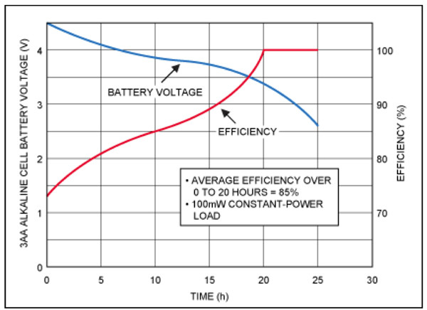
Figure 1 shows how the efficiency varies as the battery voltage drops in a system using three AA-sized alkaline batteries (at 100 mW constant power loads).

Notice how the regulator’s efficiency increases toward the dropout voltage (Courtesy of Maxim).
Although the efficiency with fully charged batteries is around 73 percent, the average efficiency across the discharge cycle is 85 percent. That’s the number that should be compared with the equivalent figure for a switching regulator, the efficiency of which won’t increase as the battery voltage falls.
Again, referring to Figure1, we see that after 20 hours, while the batteries still have some charge, the difference in input and output voltages is too small for the device to regulate and it ceases operation. In total, the cumulative amount of battery energy that has been used to actually power the product is:
Average regulation efficiency x battery energy percentage used before failure = 85 x 80 = 68 percent.
Selecting a chip with a lower dropout voltage capability ensures more of the battery’s charge is used up and, hence, improves efficiency.
“Dropout” is defined as the difference between the input and output voltage just before regulation ceases. For the example shown in Figure 1, if the linear regulator is swapped for a device with an improved dropout voltage (from 3.4 to 3.0 V) an extra 2.5 hours can be extracted from the batteries and the battery energy usage improves to:
85 x 90 = 76.5 percent¹
Check the manufacturers’ datasheets very carefully, because some so-called “low-dropout” (LDO) devices can feature input/output voltage differences that are quite large. That can mean the lights go out while the batteries still hold a lot of charge. (Note that the dropout voltage will vary depending on the load voltage.)
What’s available?
The design engineer looking to take advantage of a linear regulator’s advantages for certain applications is likely to be spoiled for choice. Among the LDO devices for portable applications, for instance, there are dozens of devices to suit a wide range of input and output voltages.
Maxim’s “Ultra-Low Quiescent Current” MAX15006/7 linear regulators, for example, offer adjustable outputs from 1.8 to 10 V and a dropout voltage of 300 mV.
Texas Instruments offers a wide range of LDO linear regulators, including the TPS71334. The chip is available with fixed or adjustable output voltage options (from 1.2 to 5.5 V) and the company says dropout voltage is 125 mV (at 250 mA). The device is tailored for noise sensitive and RF applications.

dropout voltage of 400 mV at 200 mA.
Linear Technology’s LTC 1844 Series linear regulators can operate from input voltages down to 1.6 V and have an adjustable output voltage range from 1.25 to 6 V. According to the datasheet, typical output noise is only 30 µVrms and typical dropout is 0.135 V at 150 mA. The chip is designed for portable instruments and battery-powered applications.
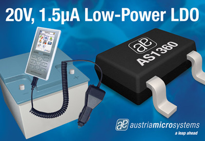
For its part, austriamicrosystems offers the AS1360 as part of its LDO linear regulator range. This chip (Figure 2) is a low-power linear voltage regulator designed to deliver up to 250 mA while consuming only 1.5 μA of quiescent current. The device is available in fixed output voltages from 1.8 to 5.0 V and features a dropout voltage of 400 mV (at 200 mA).
Summary
Linear regulators have the advantage of very "clean" output with little noise introduced into their DC output, but they can be much less efficient than switching converters (though the linear regulator’s efficiency increases toward the dropout voltage), and are unable to step-up the input voltage like their switched counterparts. Nonetheless, there are applications where the linear regulator has the upper hand. This article presented a comparison between linear and switching regulators, discussed key parameters and provided examples of available product. For more information on the parts mentioned, use the links provided to access product pages on the Digi-Key website.
References:
- “Linear Regulators in Portable Applications,” Application Note 751, Maxim.
Disclaimer: The opinions, beliefs, and viewpoints expressed by the various authors and/or forum participants on this website do not necessarily reflect the opinions, beliefs, and viewpoints of Digi-Key Corporation or official policies of Digi-Key Corporation.


Diskussion (0 Kommentare)