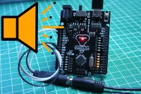
VU Meter With No Display?

You want to visualize your music but you don't have a display to use? Or maybe you don't want to bother assembling one? Here is a simple way to visualize your audio in a mesmerizing way.
You only need a few things for this project to get started.-A GlowDuino Uno board to have a display for your music:
https://www.glowduino.com/shop/p/uno
or at:
https://www.tindie.com/products/glowduino/glowduino-uno-a-better-arduino/
-And an audio jack for audio input:
https://amz.run/6QMH
In addition, if you don't already have, then some generic female jumper cables and an aux cable to connect the circuit to a source:
https://amz.run/6QMI
1)
To start assembling, you need to consider the pinout of the audio jack. On most connectors, the output pins are marked with L, G, and R, from which you know the left, ground, and right channel output of the connector. If there are no such markings on your connector, you can use a multimeter in continuity mode to find the corresponding pins. On a standard 3-pin audio jack, the tip of the connector is the Left channel, the middle ring is the Right channel, and the base of the connector is the Ground pin. You need to connect these pins of the audio jack to the A6, and A7. Lastly, run a wire between the ground pins of the connector and the microcontroller.
2)
To finish the setup, you need to upload the program to your GlowDuino board. Download and open the included "GDU_VU_Meter_Code.txt" file and copy its content to your Arduino IDE software.
Here if you may, you can change the used pins and can also change whether the audio is displayed as mono or stereo. Once you explored what the program can do, you can hit upload and load the program to your board.
3)
It's ready! If you plug your audio jack into the connector, you will see the mesmerizing waves of music on your GlowDuino board without any added external display. Prop it up on your desk or build it into an enclosure to make it a permanent decoration in your room.
If you have built this project or simply want to share your opinion, then leave a comment for us here or post about it in our Facebook group!
https://www.facebook.com/groups/glowduino


Diskussion (0 Kommentare)